Non-equilibrium pulling
When the distance between two groups is changed continuously, work is applied to the system, which means that the system is no longer in equilibrium. Although in the limit of very slow pulling the system is again in equilibrium, for many systems this limit is not reachable within reasonable computational time. However, one can use the Jarzynski relation 135 to obtain the equilibrium free-energy difference \(\Delta G\) between two distances from many non-equilibrium simulations:
where \(W_{AB}\) is the work performed to force the system along one path from state A to B, the angular bracket denotes averaging over a canonical ensemble of the initial state A and \(\beta=1/k_B T\).
The pull code
The pull code The pull code applies forces or constraints between the centers of mass of one or more pairs of groups of atoms. Each pull reaction coordinate is called a “coordinate” and it operates on usually two, but sometimes more, pull groups. A pull group can be part of one or more pull coordinates. Furthermore, a coordinate can also operate on a single group and an absolute reference position in space. The distance between a pair of groups can be determined in 1, 2 or 3 dimensions, or can be along a user-defined vector. The reference distance can be constant or can change linearly with time. Normally all atoms are weighted by their mass, but an additional weighting factor can also be used.
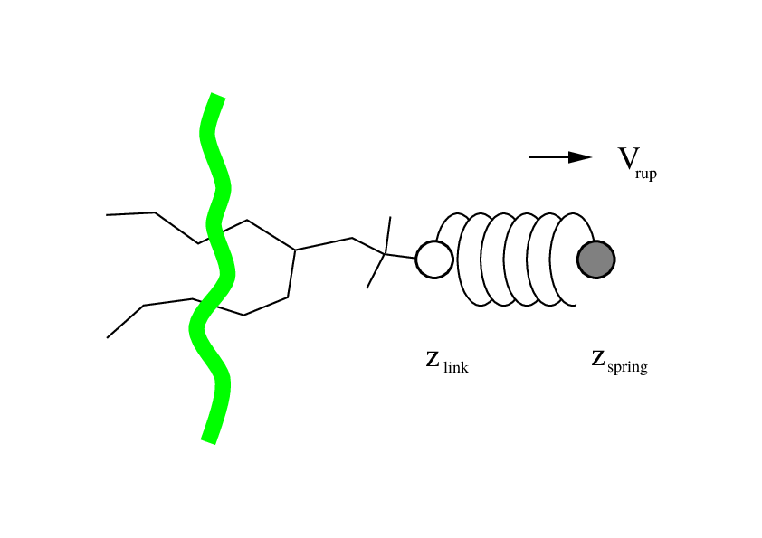
Fig. 37 Schematic picture of pulling a lipid out of a lipid bilayer with umbrella pulling. \(V_{rup}\) is the velocity at which the spring is retracted, \(Z_{link}\) is the atom to which the spring is attached and \(Z_{spring}\) is the location of the spring.
Several different pull types, i.e. ways to apply the pull force, are supported, and in all cases the reference distance can be constant or linearly changing with time.
- Umbrella pulling A harmonic potential is applied between the centers of mass of two groups. Thus, the force is proportional to the displacement.
- Constraint pulling The distance between the centers of mass of two groups is constrained. The constraint force can be written to a file. This method uses the SHAKE algorithm but only needs 1 iteration to be exact if only two groups are constrained.
- Constant force pulling A constant force is applied between the centers of mass of two groups. Thus, the potential is linear. In this case there is no reference distance of pull rate.
- Flat bottom pulling Like umbrella pulling, but the potential and
force are zero for coordinate values below
(
pull-coord?-type = flat-bottom) or above (pull-coord?-type = flat-bottom-high) a reference value. This is useful for restraining e.g. the distance between two molecules to a certain region.
In addition, there are different types of reaction coordinates,
so-called pull geometries. These are set with the mdp
option pull-coord?-geometry.
Definition of the center of mass
In GROMACS, there are three ways to define the center of mass of a group. The standard way is a “plain” center of mass, possibly with additional weighting factors. With periodic boundary conditions it is no longer possible to uniquely define the center of mass of a group of atoms. Therefore, a reference atom is used. For determining the center of mass, for all other atoms in the group, the closest periodic image to the reference atom is used. This uniquely defines the center of mass. By default, the middle (determined by the order in the topology) atom is used as a reference atom, but the user can also select any other atom if it would be closer to center of the group.
When there are large pull groups, such as a
lipid bilayer, pull-pbc-ref-prev-step-com can be used to avoid potential
large movements of the center of mass in case that atoms in the pull group
move so much that the reference atom is too far from the intended center of mass.
With this option enabled the center of mass from the previous step is used,
instead of the position of the reference atom, to determine the reference position.
The position of the reference atom is still used for the first step. For large pull
groups it is important to select a reference atom that is close to the intended
center of mass, i.e. do not use pull-group?-pbcatom = 0.
For a layered system, for instance a lipid bilayer, it may be of
interest to calculate the PMF of a lipid as function of its distance
from the whole bilayer. The whole bilayer can be taken as reference
group in that case, but it might also be of interest to define the
reaction coordinate for the PMF more locally. The mdp
option pull-coord?-geometry = cylinder does not use all
the atoms of the reference group, but instead dynamically only those
within a cylinder with radius pull-cylinder-r around the
pull vector going through the pull group. This only works for distances
defined in one dimension, and the cylinder is oriented with its long
axis along this one dimension. To avoid jumps in the pull force,
contributions of atoms are weighted as a function of distance (in
addition to the mass weighting):
Note that the radial dependence on the weight causes a radial force on both cylinder group and the other pull group. This is an undesirable, but unavoidable effect. To minimize this effect, the cylinder radius should be chosen sufficiently large. The effective mass is 0.47 times that of a cylinder with uniform weights and equal to the mass of uniform cylinder of 0.79 times the radius.
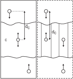
Fig. 38 Comparison of a plain center of mass reference group versus a cylinder reference group applied to interface systems. C is the reference group. The circles represent the center of mass of two groups plus the reference group, \(d_c\) is the reference distance.
For a group of molecules in a periodic system, a plain reference group might not be well-defined. An example is a water slab that is connected periodically in \(x\) and \(y\), but has two liquid-vapor interfaces along \(z\). In such a setup, water molecules can evaporate from the liquid and they will move through the vapor, through the periodic boundary, to the other interface. Such a system is inherently periodic and there is no proper way of defining a “plain” center of mass along \(z\). A proper solution is to using a cosine shaped weighting profile for all atoms in the reference group. The profile is a cosine with a single period in the unit cell. Its phase is optimized to give the maximum sum of weights, including mass weighting. This provides a unique and continuous reference position that is nearly identical to the plain center of mass position in case all atoms are all within a half of the unit-cell length. See ref 136 for details.
When relative weights \(w_i\) are used during the calculations, either by supplying weights in the input or due to cylinder geometry or due to cosine weighting, the weights need to be scaled to conserve momentum:
where \(m_j\) is the mass of atom \(j\) of the group. The mass of the group, required for calculating the constraint force, is:
The definition of the weighted center of mass is:
From the centers of mass the AFM, constraint, or umbrella force \(\mathbf{F}_{\!com}\) on each group can be calculated. The force on the center of mass of a group is redistributed to the atoms as follows:
Definition of the pull direction
The most common setup is to pull along the direction of the vector
containing the two pull groups, this is selected with
pull-coord?-geometry = distance. You might want to pull
along a certain vector instead, which is selected with
pull-coord?-geometry = direction. But this can cause
unwanted torque forces in the system, unless you pull against a
reference group with (nearly) fixed orientation, e.g. a membrane protein
embedded in a membrane along x/y while pulling along z. If your
reference group does not have a fixed orientation, you should probably
use pull-coord?-geometry = direction-relative, see
Fig. 39. Since the potential now depends
on the coordinates of two additional groups defining the orientation,
the torque forces will work on these two groups.

Fig. 39 The pull setup for geometry direction-relative. The
“normal” pull groups are 1 and 2. Groups 3 and 4 define the pull
direction and thus the direction of the normal pull forces (red).
This leads to reaction forces (blue) on groups 3 and 4, which are
perpendicular to the pull direction. Their magnitude is given by the
“normal” pull force times the ratio of \(d_p\) and the distance
between groups 3 and 4.
Definition of the angle and dihedral pull geometries
Four pull groups are required for pull-coord?-geometry =
angle. In the same way as for geometries with two groups, each
consecutive pair of groups \(i\) and \(i+1\) define a vector
connecting the COMs of groups \(i\) and \(i+1\). The angle is
defined as the angle between the two resulting vectors. E.g., the
mdp option pull-coord?-groups = 1 2 2 4
defines the angle between the vector from the COM of group 1 to the COM
of group 2 and the vector from the COM of group 2 to the COM of group 4.
The angle takes values in the closed interval [0, 180] deg. For
pull-coord?-geometry = angle-axis the angle is defined
with respect to a reference axis given by
pull-coord?-vec and only two groups need to be given.
The dihedral geometry requires six pull groups. These pair up in the
same way as described above and so define three vectors. The dihedral
angle is defined as the angle between the two planes spanned by the two
first and the two last vectors. Equivalently, the dihedral angle can be
seen as the angle between the first and the third vector when these
vectors are projected onto a plane normal to the second vector (the axis
vector). As an example, consider a dihedral angle involving four groups:
1, 5, 8 and 9. Here, the mdp option
pull-coord?-groups = 8 1 1 5 5 9 specifies the three
vectors that define the dihedral angle: the first vector is the COM
distance vector from group 8 to 1, the second vector is the COM distance
vector from group 1 to 5, and the third vector is the COM distance
vector from group 5 to 9. The dihedral angle takes values in the
interval (-180, 180] deg and has periodic boundaries.
Limitations
There is one theoretical limitation: strictly speaking, constraint
forces can only be calculated between groups that are not connected by
constraints to the rest of the system. If a group contains part of a
molecule of which the bond lengths are constrained, the pull constraint
and LINCS or SHAKE bond constraint algorithms should be iterated
simultaneously. This is not done in GROMACS. This means that for
simulations with constraints = all-bonds in the mdp file pulling is,
strictly speaking, limited to whole molecules or groups of molecules. In
some cases this limitation can be avoided by using the free energy code,
see sec. Calculating a PMF using the free-energy code. In practice, the errors caused by not iterating
the two constraint algorithms can be negligible when the pull group
consists of a large amount of atoms and/or the pull force is small. In
such cases, the constraint correction displacement of the pull group is
small compared to the bond lengths.