Computational Electrophysiology
The Computational Electrophysiology (CompEL) protocol 147 allows the simulation of ion flux through membrane channels, driven by transmembrane potentials or ion concentration gradients. Just as in real cells, CompEL establishes transmembrane potentials by sustaining a small imbalance of charges \(\Delta q\) across the membrane, which gives rise to a potential difference \(\Delta U\) according to the membrane capacitance:
The transmembrane electric field and concentration gradients are controlled by mdp options, which allow the user to set reference counts for the ions on either side of the membrane. If a difference between the actual and the reference numbers persists over a certain time span, specified by the user, a number of ion/water pairs are exchanged between the compartments until the reference numbers are restored. Alongside the calculation of channel conductance and ion selectivity, CompEL simulations also enable determination of the channel reversal potential, an important characteristic obtained in electrophysiology experiments.
In a CompEL setup, the simulation system is divided into two compartments A and B with independent ion concentrations. This is best achieved by using double bilayer systems with a copy (or copies) of the channel/pore of interest in each bilayer (Fig. 49 A, B). If the channel axes point in the same direction, channel flux is observed simultaneously at positive and negative potentials in this way, which is for instance important for studying channel rectification.
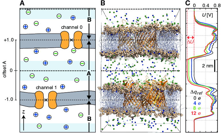
Fig. 49 Typical double-membrane setup for CompEL simulations (A, B). Ion/water molecule exchanges will be performed as needed between the two light blue volumes around the dotted black lines (A). Plot (C) shows the potential difference \(\Delta U\) resulting from the selected charge imbalance \(\Delta q_{ref}\) between the compartments.
The potential difference \(\Delta U\) across the membrane is easily calculated with the gmx potential utility. By this, the potential drop along \(z\) or the pore axis is exactly known in each time interval of the simulation (Fig. 49 C). Type and number of ions \(n_i\) of charge \(q_i\), traversing the channel in the simulation, are written to the swapions.xvg output file, from which the average channel conductance \(G\) in each interval \(\Delta t\) is determined by:
The ion selectivity is calculated as the number flux ratio of different species. Best results are obtained by averaging these values over several overlapping time intervals.
The calculation of reversal potentials is best achieved using a small set of simulations in which a given transmembrane concentration gradient is complemented with small ion imbalances of varying magnitude. For example, if one compartment contains 1M salt and the other 0.1M, and given charge neutrality otherwise, a set of simulations with \(\Delta q = 0\,e\), \(\Delta q = 2\,e\), \(\Delta q = 4\,e\) could be used. Fitting a straight line through the current-voltage relationship of all obtained \(I\)-\(U\) pairs near zero current will then yield \(U_{rev}\).
Usage
The following mdp options control the CompEL protocol:
swapcoords     = Z        ; Swap positions: no, X, Y, Z
swap-frequency = 100      ; Swap attempt frequency
Choose Z if your membrane is in the \(xy\)-plane
(Fig. 49). Ions will be exchanged
between compartments depending on their \(z\)-positions alone.
swap-frequency determines how often a swap attempt will
be made. This step requires that the positions of the split groups, the
ions, and possibly the solvent molecules are communicated between the
parallel processes, so if chosen too small it can decrease the
simulation performance. The Position swapping entry in
the cycle and time accounting table at the end of the
md.log file summarizes the amount of runtime spent in
the swap module.
split-group0   = channel0 ; Defines compartment boundary
split-group1   = channel1 ; Defines other compartment boundary
massw-split0   = no       ; use mass-weighted center?
massw-split1   = no
split-group0 and split-group1 are two
index groups that define the boundaries between the two compartments,
which are usually the centers of the channels. If
massw-split0 or massw-split1 are set to
yes, the center of mass of each index group is used as
boundary, here in \(z\)-direction. Otherwise, the geometrical
centers will be used (\(\times\) in
Fig. 49 A). If, such as here, a membrane
channel is selected as split group, the center of the channel will
define the dividing plane between the compartments (dashed horizontal
lines). All index groups must be defined in the index file.
If, to restore the requested ion counts, an ion from one compartment has
to be exchanged with a water molecule from the other compartment, then
those molecules are swapped which have the largest distance to the
compartment-defining boundaries (dashed horizontal lines). Depending on
the ion concentration, this effectively results in exchanges of
molecules between the light blue volumes. If a channel is very
asymmetric in \(z\)-direction and would extend into one of the swap
volumes, one can offset the swap exchange plane with the
bulk-offset parameter. A value of 0.0 means no offset
\(b\), values \(-1.0 < b < 0\) move the swap exchange plane
closer to the lower, values \(0 < b < 1.0\) closer to the upper
membrane. Fig. 49 A (left) depicts that
for the A compartment.
solvent-group  = SOL      ; Group containing the solvent molecules
iontypes       = 3        ; Number of different ion types to control
iontype0-name  = NA       ; Group name of the ion type
iontype0-in-A  = 51       ; Reference count of ions of type 0 in A
iontype0-in-B  = 35       ; Reference count of ions of type 0 in B
iontype1-name  = K
iontype1-in-A  = 10
iontype1-in-B  = 38
iontype2-name  = CL
iontype2-in-A  = -1
iontype2-in-B  = -1
The group name of solvent molecules acting as exchange partners for the
ions has to be set with solvent-group. The number of
different ionic species under control of the CompEL protocol is given by
the iontypes parameter, while
iontype0-name gives the name of the index group
containing the atoms of this ionic species. The reference number of ions
of this type can be set with the iontype0-in-A and
iontype0-in-B options for compartments A and B,
respectively. Obviously, the sum of iontype0-in-A and
iontype0-in-B needs to equal the number of ions in the
group defined by iontype0-name. A reference number of
-1 means: use the number of ions as found at the
beginning of the simulation as the reference value.
coupl-steps    = 10       ; Average over these many swap steps
threshold      = 1        ; Do not swap if < threshold
If coupl-steps is set to 1, then the momentary ion
distribution determines whether ions are exchanged.
coupl-steps > 1 will use the time-average of ion
distributions over the selected number of attempt steps instead. This
can be useful, for example, when ions diffuse near compartment
boundaries, which would lead to numerous unproductive ion exchanges. A
threshold of 1 means that a swap is performed if the
average ion count in a compartment differs by at least 1 from the
requested values. Higher thresholds will lead to toleration of larger
differences. Ions are exchanged until the requested number \(\pm\)
the threshold is reached.
cyl0-r         = 5.0      ; Split cylinder 0 radius (nm)
cyl0-up        = 0.75     ; Split cylinder 0 upper extension (nm)
cyl0-down      = 0.75     ; Split cylinder 0 lower extension (nm)
cyl1-r         = 5.0      ; same for other channel
cyl1-up        = 0.75
cyl1-down      = 0.75
The cylinder options are used to define virtual geometric cylinders
around the channel’s pore to track how many ions of which type have
passed each channel. Ions will be counted as having traveled through a
channel according to the definition of the channel’s cylinder radius,
upper and lower extension, relative to the location of the respective
split group. This will not affect the actual flux or exchange, but will
provide you with the ion permeation numbers across each of the channels.
Note that an ion can only be counted as passing through a particular
channel if it is detected within the defined split cylinder in a swap
step. If swap-frequency is chosen too high, a particular
ion may be detected in compartment A in one swap step, and in
compartment B in the following swap step, so it will be unclear
through which of the channels it has passed.
A double-layered system for CompEL simulations can be easily prepared by
duplicating an existing membrane/channel MD system in the direction of
the membrane normal (typically \(z\)) with
gmx editconf -translate 0 0 <l_z>, where l_z is the box
length in that direction. If you have already defined index groups for
the channel for the single-layered system, gmx make_ndx
-n index.ndx -twin will provide you with the groups for the
double-layered system.
To suppress large fluctuations of the membranes along the swap direction, it may be useful to apply a harmonic potential (acting only in the swap dimension) between each of the two channel and/or bilayer centers using umbrella pulling (see section Collective variables: the pull code).
Multimeric channels
If a split group consists of more than one molecule, the correct PBC image of all molecules with respect to each other has to be chosen such that the channel center can be correctly determined. GROMACS assumes that the starting structure in the tpr file has the correct PBC representation. Set the following environment variable to check whether that is the case:
GMX_COMPELDUMP: output the starting structure after it has been made whole to pdb file.